
In industrial processes involving gases, in the energy industry, process engineering, production or chemistry, for example, whose goal is to optimize, to provide quality assurance or to avert danger, using online gas analysis allows optimal process control.
The term “online” in this context means that the delay between concentration change in the process line and the measured signal change is so short that the measurement signal always represents the instantaneous concentration such that it can still be properly counteracted. This also implies that analysis is continuous in the sense that relevant changes in concentration are not obscured or even go undetected.
Such devices can operate in situ by being directly exposed to the process gas, often by use of a filter or frit, or by sending a light beam directly through the process gas, e.g. for in situ photometers.
The second possibility is to remove the gas, to transport it, if necessary to condition it and then to forward the analysis. After that, it can be fed back or discarded. This method is called extractive gas analysis.
Both methods have their justification and specific advantages and disadvantages.
The in situ analysis is often fast, not corrupted by treatment, and usually less additional components are necessary. On the other hand, the requirements for selectivity, resistance to the process conditions and on-site adjustment are often unmanageable.
The advantages of extractive analysis are the ability to condition the sample for analysis, e.g. remove interfering components such as dust and water vapor. Pressure and temperature can be brought to a level more easily accessible for analysis.
Of course, this advantage can also be detrimental if the procedure during sample conditioning falsifies the measured value, e.g. in that the measuring component is partially washed out in a cooler used for drying the gas.
We will focus on extractive analytics in the following paragraphs.
Planning can start by defining the sampling point, which of course is influenced by the measuring task itself. First, it must be clarified whether the gas sample of interest is actually present at the place of extraction. There, all mixing processes and chemical reactions should be completed. Sampling points behind coolers or separators are particularly suitable for analytical measurements in which mean values in the material balance are of greater interest than determining momentary fluctuations. In most cases, the medium being measured is in an easy-to-process state for removal at these locations.
In larger gas channels, concentration arrangement in layers may also occur laterally to the flow. Peripheral currents or for example the gas in a calm zone may not be representative and could then lead to erroneous analysis. At this point, it may be necessary to determine during preliminary tests the suitable location for taking a representative sample by scanning the line cross-section.
Often used are gas sample probes. They offer the option of a pre-separation: for example, due to their inertia, particles, drops and aerosols can be kept out of the analysis system by extracting in counter-current. If, on the other hand, you want to have such substances in the sample, you have to extract isokinetically with the flow. Often filters are mounted inside the probe, they can be heated together with the probe to avoid sooting. In many simple applications T-pieces are used, which emerge at right angles or acute-angled from the main flow to collect problem-free sample gases.
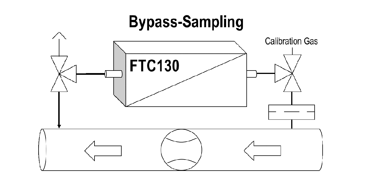
It is particularly easy to supply the analyzer with gas in a bypass arrangement that generates the bypass current through a choke in the main flow. This is shown schematically in Figure 1. Three-way valves are mounted to feed and remove the calibration gas. The influx is equipped with a filter. If necessary, a column cooler can also be integrated in front of the analyzer’s gas inlet.
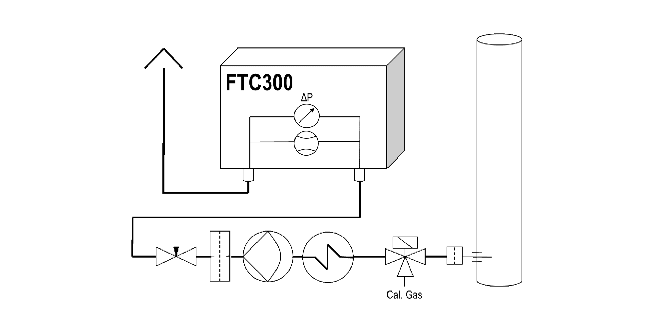
A sample gas pump is used if there is no overpressure for gas transport. If pulsed pumps are used, there is a risk that excessive pulsation will distort the measured value, either due to signal noise induced by turbulence or even offset of the signal due to pressure and flow dependencies. Therefore, it is often necessary to decouple the analyzer from the pump surges by integrating a flow-limiting element between the pump and the analyzer. If the pump is throttled on the pressure side by a needle valve, as shown in Figure 2, no pump should be used, which will generate a high pressure, as this may lead to unwanted reactions, such as condensation. Simple magnetic piston pumps are particularly suitable for removal from systems that are under atmospheric pressure. Of course, variable pumps can also be used to adjust proper flow without pressure spikes. Measuring and, if necessary, monitoring the flow and adjusting the needle valve correctly takes place (see Fig. 2) by determining the pressure drop across a laminar flow restrictor.
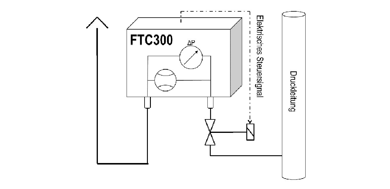
If the process gas is under sufficient overpressure relative to the analyzer’s outlet, a control of the flow rate is suitable. If the pressure is too high or is fluctuating, then the pressure needs to be reduced and stabilized using a pressure regulator or a closed loop flow control. This closed loop control is particularly simple using the FTC300flow device, which measures the current gas flow and generates an output signal for a proportional valve that keeps the flow constant. This set-up is shown in Figure 3.
If gas removal and refeeding are required under the same but high pressure, then so-called gas circulators are suitable. In these devices the gas path is fully encapsulated and therefore pressure-resistant. Their feeding rotary valves are driven magnetically coupled. Measuring devices FTC300 and FTC130 can be charged with up to 20 bar.
In order to make the sample accessible to a continuous and permanent analysis, it is often necessary to condition the sample; this is referred to as sample preparation and usually involves the removal of interfering constituents.
All forms of separation and preparation must be performed so that the sample remains representative of the gas composition in the process line. If the gas composition changes due to the sample preparation procedure, this must be done necessarily reproducible to obtain a properly corrected value representative for the concentration in the process line. For example the reduction of the total gas volume using a gas cooler must be taken into account to correct the measured value.
Physical and chemical processes are used for sample preparation.
Physical processes are:
For particle separation mechanical filters are most commonly used and sample gas coolers for removing condensable components.
Chemical processes can convert problematic substances through catalysis, chemical bonding or adsorption removing them totally from the sample gas. This includes for example:
It should be noted that these compounds are consumables and have to be exchanged or reprocessed before the end of their capacity.
To ensure the quality of the analysis, the analyzer must be checked with calibration gases and readjusted if necessary. When feeding the calibration gases in, keep in mind that cooler, filter, ad- and absorber may modify the gas composition, because they may desorb moisture. Feeding the adjusting gas should be carried out with the same treatment like the sample gas during the sample preparation procedure. This situation is shown in Figure 2 where the calibration gas is feed in before the sample gas cooler. If it is to be expected that the gas path will dry out during the period of the adjustment process, then the calibration gas should be supplied in a moistened state. Recirculating the gas into the process is to be suspended during the adjustment if this causes contamination.
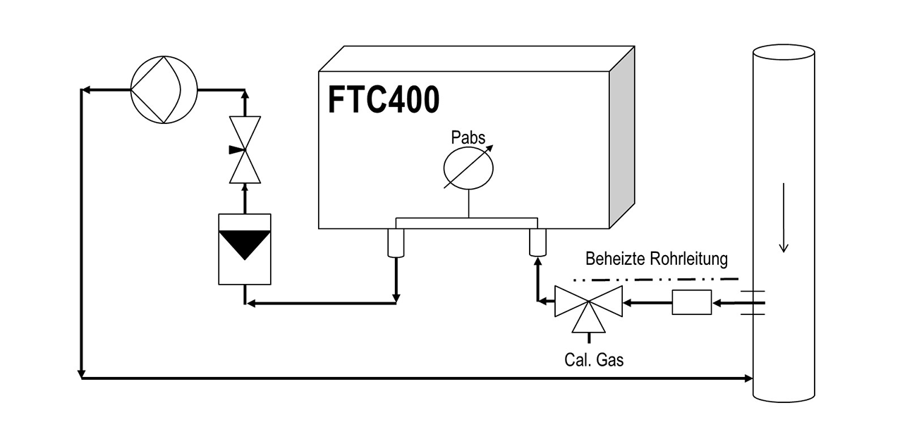
Compensating the pressure influence is necessary for many measurements and adjustments that do not take place under constant pressure conditions. To assess this, one should be aware that the reading of photometers varies approximately in proportion to the pressure. A pressure change of 50 hPa, which can take place under atmospheric conditions as well, leads to a reading change of about 5%. In the case of measuring instruments based on the thermal conductivity principle, pressure compensation in the range above 800 hPa (absolute) is generally not necessary. The FTC 400, shown in Figure 4, with the integrated IR measurement is therefore equipped with a pressure compensation unit. It is active during the measurement and adjustment as well in order to correct the displayed measured value— on basis of the standard pressure.
In analysis technology, the response time of an analysis system is usually specified as the T90 time. It is defined as the time it takes between a sudden stepwise change of the quantity to be measured and the point in time it takes to indicate 90% of the final value. In this definition, the T90 time contains the dead time, which is sometimes specified separately. The dead time is given by the time elapsed from the stepwise change in the process of the quantity to be measured to the 10% of final reading.
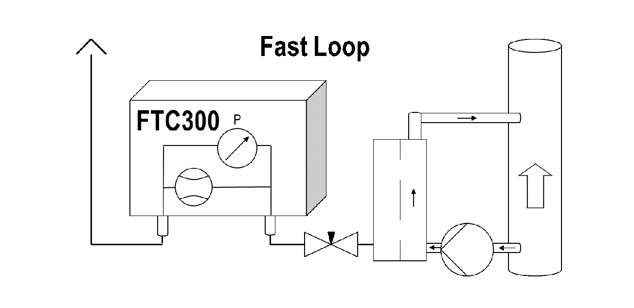
If a rapid response of the measuring system is required, the sampling point should not be unnecessarily far downstream of the reaction zone. In addition, the sample quantity must be large enough to keep the residence time of the sample in the treatment system sufficiently short. In the analysis piping, there are always plug flows which are characterized by the fact that the gas propagates at the speed v = (dV/dt)/Q, where dV/dt means the sample quantity per time and Q the cross-section of the pipeline. Thus, small-tube cross sections for short response times are useful, as well. For flow rates in the range of about 1l/min., we recommend a 1/8″pipe with a 2 mm inner diameter. Large expansions in the cross section, e.g. through pumps, coolers, separators and filters, often behave like mixing reactors, which—as a rule of thumb—require 4 times their volume to deliver a stepwise change in concentration at the entrance to 90% of its final value at the output. If possible, it is important to avoid such “mixing reactors” in the sampling path upstream of the analyzer or at least to make them small. Some polar gases show a tendency—especially in combination with moisture—to be adsorbed on surfaces. This can lead to chromatographic effects. Therefore, inert smooth materials should be used. Heating the pipes can also reduce this effect. Figure 4 shows an optimized set-up for the sample gas with minimal response time. Sometimes a “fast-loop” is helpful (see Figure 5) if long sample gas paths are present and high flow rates are available. A sample quantity that is too big for analysis is taken from the mainstream and is fed into a filter located close to the analyzer. A suitable sample stream is then extracted out of the filter for analysis. Thereby dust, aerosols and liquids are separated. The separated material is removed by the fast-loop flow; this set-up is also referred to as “cross-flow filtration.”
Stainless steel components, like LF316Ti, are suitable for permeation-proof, pressure-resistant and relatively corrosion-resistant arrangements. Other even more corrosive resistant alloys as HASTELLOY® can be applied for highly aggressive gases.
PTFE or PFA are particularly inert but quite permeable and therefore not suitable for trace gas analysis of oxygen, for example. This is more or less true for all polymers.
Please do not hesitate to contact us if you would like a quote or have a question. You can reach us via the contact form and via the e-mail address below. Before making an offer, we clarify the requirements with a form for the measuring task. This way we want to make sure that you will receive the device from us that best fits your measuring task.